No Load, Still Paying: How Standby Pressure Drains Hydraulic Power Units
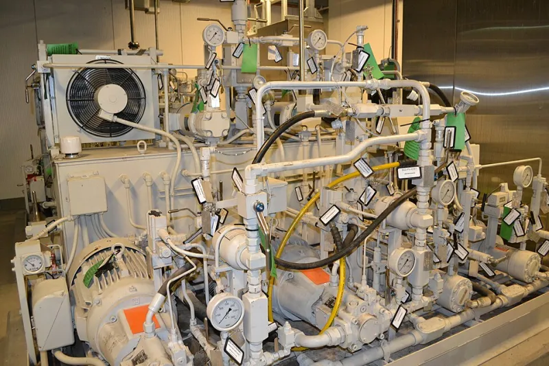
Photo: PEO ACWA, CC BY 2.0, via Wikimedia Commons
A hydraulic power unit can be busy doing nothing. Between shifts, during breaks and over weekends, a fixed-displacement pump may continue to turn, sending oil over a relief valve because no actuator is demanding flow. The machine is not producing, but it is still consuming electricity and generating heat. In 2026, with UK industrial energy costs under close scrutiny, that standby pressure is worth measuring rather than assuming.
The issue is not limited to old plant. A power unit can be well maintained and still run inefficiently because its control philosophy was designed for a different energy climate. The audit question is simple: how many hours does the pump run without useful demand, and what pressure is it holding during those hours?
What standby pressure is costing
With a fixed-displacement pump, flow is roughly constant whenever the drive motor runs. If the machine is idle, that flow must go somewhere. It typically passes over the main relief valve at the set pressure. The hydraulic power lost in that condition is proportional to pressure multiplied by flow. The electrical input is higher still because of pump and motor efficiency.
As an illustrative example, consider a pump delivering 20 litres per minute at a relief setting of 100 bar. The hydraulic power is approximately 3.3 kW. If the overall pump and motor efficiency is around 0.7, the electrical input is approximately 4.7 kW. If the unit sits in standby for 4,000 hours a year, the annual electricity use is in the region of 19 MWh. At an assumed industrial rate of 20 pence per kWh, that is around £3,800 before any allowance for cooling fans or downstream losses. The figures will differ by site, but the principle holds: standby hours can dominate the energy profile of a machine that appears idle.
The cost is not only electrical. Oil held at pressure over a relief valve heats up, which increases the load on coolers and accelerates oil ageing. The relief valve itself may wear or become contaminated, leading to drift in the set pressure. A unit that is quiet in production but hot and noisy between shifts is often telling you that standby pressure is doing unnecessary work.
Measure before deciding
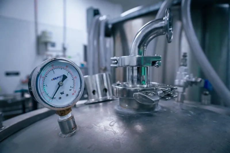
An audit should begin with a representative week of data. Install a calibrated pressure gauge or logger at the pump outlet and, where accessible, at the relief valve. Record pump run-hours from a drive contactor, a pressure switch, a cycle counter or a current clamp on the motor supply. The aim is to separate production time, idle-ready time, standby time and off time.
A simple state log is often enough. Note when the machine is making parts, when it is held ready between cycles, when it is left running during breaks and when it is shut down. Record the pressure in each state. If the pump is running at full relief pressure with no actuator demand, that is a standby loss. If the pressure falls and the pump cycles, an accumulator or a leaking valve may be involved. If the pump runs at low pressure but high flow, check for bypass or a cooling circuit that is permanently energised.
Once the standby hours and pressure are known, calculate the avoidable energy. Use the pump flow, the relief setting and an efficiency estimate, then multiply by standby hours. Compare that figure with the cost of a corrective measure. This is more reliable than guessing from the nameplate.
Where losses hide
Common avoidable losses include a fixed-displacement pump with no unloading facility, a relief valve that is set higher than the process requires, an accumulator that has lost precharge and causes repeated pump cycling, and internal leakage through sequencing or directional valves. Control logic can also keep a pump running when the machine is not scheduled to produce. A cooler or fan running continuously during standby is a separate but related load.
It is worth checking the relief setting against the actual duty. A valve set at 100 bar because a cylinder once needed it may be holding pressure unnecessarily high for a machine that now runs at 70 bar. Reducing the setting within the manufacturer's limits can cut standby power without affecting performance, provided the change is properly assessed and recorded.
Retrofit options and when they pay
There are three main routes to reducing standby pressure. The first is an unloading valve or pump control that senses demand and lets the pump discharge at low pressure when no actuator is calling for flow. This is often the most cost-effective option for a fixed-displacement pump with a simple duty cycle. The second is an accumulator, which can store energy for intermittent demand and allow the pump to unload between cycles. This suits clamp-and-hold circuits or machines with short, repeated demands, but it requires proper sizing, precharge maintenance and safety assessment. The third is a variable-speed drive, which matches pump output to demand by changing motor speed. It can deliver substantial savings where demand varies widely, but it needs a compatible motor and pump, a minimum-speed strategy, cooling consideration and an assessment of harmonics and control response.
The decision should follow the data. If standby hours are low, fix leaks, review operating procedures and correct relief settings first. If standby hours are moderate and the duty is simple, an unloading valve may offer a short payback. If the machine has long idle periods and highly variable demand, a variable-speed drive may be worth a detailed study. If the demand is intermittent but the pump must respond quickly, an accumulator may be the better fit. None of these options should be selected without checking the duty cycle, the existing control philosophy and the maintenance capability on site.
A practical audit sequence
Begin with a week of pressure and run-hour logging. Map the machine states and calculate the standby energy. Inspect the relief valve, accumulator precharge and valve leakage. Review the control logic with the maintenance and operations teams, including shift-start and weekend routines. Then model one or two options against the measured baseline and pilot the preferred measure before committing to a full retrofit.
The standby pressure problem is easy to overlook because nothing appears to be happening. That is precisely why it deserves attention. A power unit that runs unloaded only when it needs to is not just cheaper to operate; it runs cooler, wears less and gives the maintenance team one less source of avoidable heat and pressure.