Transients in the Dark: A Logging Campaign for Hydraulic Shock Loads
The gauge is not lying, it is averaging
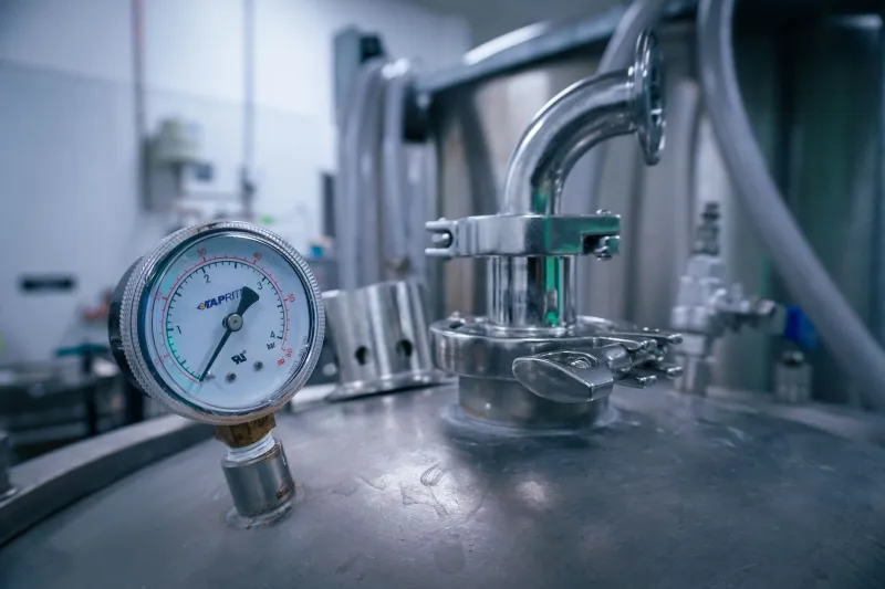
A hydraulic power unit can appear perfectly settled at 180 bar while a pressure transient of 400 bar passes through the manifold in less than the blink of an eye. A conventional Bourdon-tube gauge has neither the frequency response nor the recording discipline to capture that event. It displays a damped average, and the average is often reassuring. The damage is done by the peak.
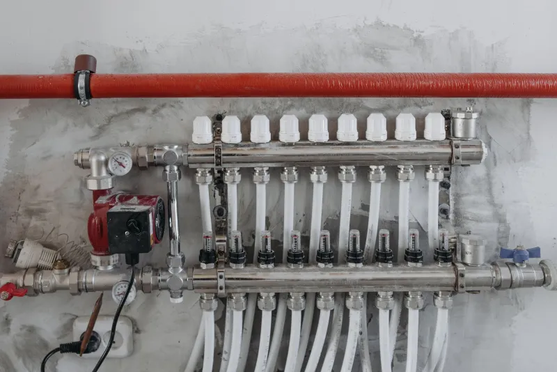
For UK maintenance teams, the problem is particularly easy to overlook in plants that run unattended overnight. A press, clamp or actuator may complete thousands of cycles without an obvious fault, yet each rapid stop can send a shock wave through valve blocks, seals and pipework. Fatigue cracks in cast-iron or aluminium manifolds frequently begin at a threaded port or internal intersection where the transient is concentrated. By the time oil is visible, the useful diagnostic window has usually closed.
A temporary logging exercise is therefore not an academic exercise. It is a reliability intervention.
Where shock loads come from
Hydraulic shock is rarely caused by one component alone. It is a system behaviour, and three mechanisms deserve particular attention.
Valve timing. A directional valve that closes a port while an actuator is still moving converts kinetic energy into a pressure rise. Centres that block flow abruptly are common culprits. The same applies to fast-switching proportional valves when the ramp is too aggressive for the moving mass.
Accumulator behaviour. An accumulator is often treated as a passive accessory. In reality it is a dynamic element. If precharge has been lost, if the bladder is damaged or if the isolation valve has been left shut, the accumulator no longer absorbs the first part of a transient. Pressure peaks rise accordingly, even though normal operating pressure may look correct.
Sudden actuator stops. Cylinder cushions, load-holding valves and quick-exhaust arrangements all influence deceleration. A cushion screw that has been wound in too far, or a load-holding valve that slams shut, can turn a routine stroke into a pressure spike. On multi-actuator circuits, the spike may appear at a manifold section that is remote from the actuator that caused it.
Choosing the logging kit
The objective is to capture short events without installing permanent instrumentation. A temporary pressure logger and a suitable transducer are usually sufficient, provided the specification is taken seriously.
Select a transducer with a frequency response well above the events of interest. A 1 kHz response is a sensible minimum for general industrial hydraulics; faster response is preferable where cartridge valves or high-speed presses are involved. The pressure range should be chosen so that expected transients do not saturate the sensor. A 0 to 600 bar transducer on a 180 bar system is not excessive if shock is suspected.
Use a logger with a pre-trigger buffer. Without it, the recording starts after the event and the rise time is lost. A buffer of five to ten seconds is normally adequate. Check that the logger sample rate is at least 1 kHz, and preferably 2 kHz or more, for the duration of each triggered capture.
Mechanical installation matters as much as electronics. Use a validated test point or a suitable adaptor at the manifold test port. Keep the connection short and rigid where possible; a long, flexible hose can damp the very transient being measured. Confirm that all adaptors and hoses are rated for the maximum pressure the system can produce, and carry out the work under a proper risk assessment by a competent person.
A trigger routine that catches events
A one-week campaign should not attempt to record continuously at high sample rates. Storage limits and data review effort make that impractical. Triggered capture is more effective.
Set the primary trigger at approximately 1.2 times the normal working pressure. If the machine runs at 180 bar, a trigger at 215 bar will catch meaningful excursions without filling the memory with pump ripple. Add a second, higher threshold if the logger supports it, so that severe events are flagged separately. Configure a pre-trigger of five seconds and a post-trigger of ten seconds. This captures the operating state before the event and the decay afterwards.
Where possible, record a digital input from the machine control system or a current clamp on the valve solenoid. This allows the pressure trace to be aligned with the command signal. Even a simple time-stamp log kept by the operator is better than pressure data with no context.
Running the audit over seven days
Day one should establish a baseline. Record normal cycles at several operating conditions and confirm that the trigger threshold is not being exceeded during routine work. Days two to four should capture production running, including start-up, shutdown and any changeover routines. Days five to seven should target the operating states most likely to generate shock: emergency stops, rapid deceleration, accumulator isolation tests and first movement after a shift change.
Keep a simple log of machine state, product or tooling, ambient conditions and any operator observations. In a damp UK workshop, ambient temperature variation can affect oil viscosity and actuator speed, so note whether the site is heated overnight. Review the captures at the end of each day rather than waiting until the end of the week; a nuisance trigger can then be corrected before it wastes several days of recording.
Reading the traces
A pressure trace is useful only when it is interpreted in the context of the cycle. Look first at peak pressure, then at rise time and duration. A short, high-amplitude spike with a fast rise is characteristic of a sudden flow interruption or actuator stop. A lower-amplitude, higher-frequency oscillation may be pump ripple or a resonance in the pipework. Repeated spikes at the same point in the cycle suggest a valve timing or control issue; random spikes suggest an operator-dependent action or an intermittent accumulator fault.
Compare the peak against the manifold rating and against the fatigue history of similar equipment. A single 350 bar spike on a 250 bar rated casting is not automatically a failure, but repeated spikes at that level deserve investigation. Look also at the decay: a slow return to normal pressure can indicate a restricted return path or a partially blocked filter.
Case study: the cracked manifold
A UK manufacturer reported a persistent weep from a manifold on a hydraulic clamping circuit. The manifold had been replaced once already, and the replacement had begun to seep within months. Normal pressure was 160 bar and the gauge showed no variation. A week-long logging campaign was arranged using two temporary transducers, one at the pump outlet and one at the clamp section of the manifold.
The logger captured peaks of 370 to 390 bar occurring immediately after clamp release. The events coincided with a rapid directional-valve shift and were more frequent on the night shift, when operators tended to run the cycle faster. Inspection found that the accumulator precharge had fallen well below specification and that the valve ramp had been set aggressively during an earlier repair. After the precharge was corrected and the valve ramp adjusted, repeat logging showed peaks below 240 bar. The seepage stopped after the manifold was replaced, and no further cracking was reported in the following months.
Making the campaign routine
The value of a logging campaign lies in what happens afterwards. Record the transducer details, trigger settings and installation points so that the exercise can be repeated. Add the capture files to the asset history. Where a transient is linked to a specific operating practice, update the standard work instruction rather than relying on individual memory.
Hydraulic shock is often invisible in normal operation, but it leaves evidence in the pressure trace. A disciplined week of triggered logging can turn a mysterious manifold failure into a measurable, correctable system behaviour.