Measuring Rod Creep: A Workshop Protocol for Hydraulic Cylinder Drift
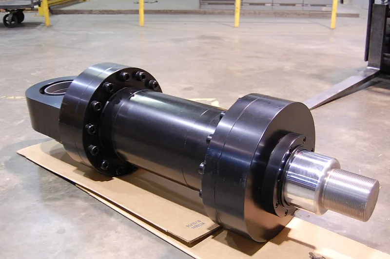
Photo: Rstom03, CC BY-SA 3.0, via Wikimedia Commons
Cylinder drift is one of the most commonly reported hydraulic faults and one of the least consistently measured. An operator reports that a rod creeps, but without a number the maintenance team cannot tell whether the movement is normal thermal settling, a worn piston seal, a leaking directional valve or a load-holding valve that is passing internally. The result is often a delayed repair or an unnecessary strip-down. This protocol uses basic workshop tools to produce a repeatable drift rate and to narrow the source of the leakage.
Why a drift rate is more useful than a description
Internal leakage stays inside the circuit. There is no external oil loss, no obvious puddle and often no pressure gauge reading that looks wrong. The visible symptom is rod movement under load, and the rate of that movement is the most useful condition indicator available to a maintenance team. A slow, stable creep may be tolerable on some applications. A rate that is increasing, or one that moves a supported load into an unsafe position, is a reliability issue that should be addressed before failure.
A measured drift rate also allows trend comparison. Two tests taken a month apart are far more informative than two subjective reports. The aim is not laboratory accuracy; it is a consistent method that any competent technician can repeat on site.
Preparing a safe and repeatable test
Safety comes before measurement. Complete a risk assessment, support or lower the load, isolate and lock off the power unit, relieve stored pressure and establish an exclusion zone. A cylinder that drifts under load can move unexpectedly. Where the machine cannot be loaded safely, use a test rig or a controlled workshop arrangement rather than improvising on a production asset.
Test at normal working temperature. Use the same rod position, the same load and the same direction of movement for each repeat. Mid-stroke is usually best because it avoids end cushions and gives room for movement in either direction. Record oil temperature at the start and end of each test. If temperature changes by more than a few degrees during the test, allow the system to stabilise and repeat, because thermal expansion and contraction can mimic leakage.
Where practical, isolate at the cylinder ports using rated line stops or caps. This is the key to separating cylinder leakage from valve leakage, and it must be done with components rated for the pressure and with a documented risk assessment.
The stopwatch procedure
- Bring the oil to normal working temperature and record it.
- Extend the rod to mid-stroke, clean the rod and fit a tape reference or magnetic scale.
- Apply a representative load, or record the existing load if the machine can be held safely.
- Isolate the cylinder and start the stopwatch at the moment of release.
- Record displacement at 1, 5, 10 and 15 minutes. If there is no movement after 15 minutes, extend the test to 30 minutes.
- Record oil temperature again at the end of the test.
- Repeat three times and calculate the average rate in mm/min.
Keep the test position and load consistent. A cylinder tested at full extension may behave differently from one tested at mid-stroke, and a test with no load may not reveal leakage that appears only under pressure.
Separating seal bypass from valve leakage
The isolation point determines what the test is measuring. With the directional valve in neutral and the cylinder lines connected, drift can come from piston-seal bypass, spool leakage in the directional valve, or a load-holding valve passing internally. Repeat the test with the cylinder ports blocked as close to the cylinder as possible. If drift continues with the cylinder ports blocked, suspect piston-seal bypass or leakage at the cylinder port connections. If drift stops when the cylinder is blocked, suspect the directional valve or downstream circuit.
Where a load-holding valve is fitted, check its pilot line and internal sealing. A load-holding valve can mask cylinder leakage or create drift of its own. Cross-port leakage at the directional valve can also produce movement without any cylinder fault, so do not condemn the cylinder until the isolation test has been repeated at the correct point.
Normalising for oil temperature
Hydraulic oil viscosity falls as temperature rises, and internal leakage generally increases with hotter, thinner oil. Do not compare tests taken at different temperatures. Record temperature with every test and compare results only within about ±5 °C unless you have manufacturer viscosity data to correct the result. Where OEM data is available, normalise the drift rate to a reference temperature such as 40 °C. Where it is not, trend the result at the same test condition rather than applying a generic correction factor.
Thermal effects can also confuse the picture. If the oil is cooling during the test, the rod may retract slightly as the oil contracts. That is not necessarily leakage. Let the system stabilise before starting the stopwatch and note any temperature drift in the record.
A simple record sheet
| Item | Record |
|---|---|
| Date and machine | |
| Cylinder reference | |
| Oil temperature at start and end | |
| Load or pressure condition | |
| Test position | |
| Isolation point | |
| Displacement at 1, 5, 10 and 15 minutes | |
| Average drift rate in mm/min | |
| Direction of drift | |
| Technician and notes |
Decision thresholds for repair or monitoring
Thresholds should be agreed for the specific machine, but a practical starting point for industrial systems is as follows. A stabilised rate below 0.5 mm/min may be monitored where the load is safely held and the trend is stable. A rate between 0.5 and 2 mm/min warrants investigation, especially if it has increased since the last test. A rate above 2 mm/min, or a rate that doubles over three consecutive tests, warrants planned repair. Any drift that moves a supported load into an unsafe position, reaches end of stroke during a shift, or prevents the load from being held should be repaired before return to service.
These figures are not universal. Cylinder size, load, oil viscosity, circuit design and the consequences of movement all matter. The value of the method is that it turns a vague report into a trend that UK maintenance teams can act on with confidence.