Between Cut-In and Cut-Out: Verifying Pressure Switches on Unattended Hydraulic Plant
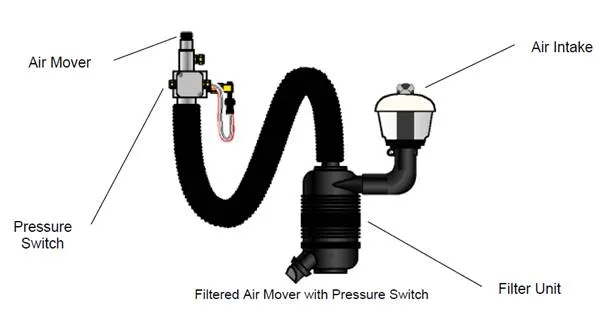
Photo: Lindsey Sh, CC BY-SA 3.0, via Wikimedia Commons
Standby hydraulic power units are often judged by their silence. If the pump is not running, the assumption is that the system is healthy and waiting. In practice, a pressure switch that has drifted by only a small margin can turn that silence into a rhythm of brief, repeated starts that wears contacts, heats oil and wastes energy without raising an obvious alarm. The fault is rarely dramatic. It sits between cut-in and cut-out, in the deadband that separates pump stop from pump start, and it is easily missed unless someone checks the switch against a known reference.
Why a drifting switch rarely announces itself
A pressure switch does not usually fail outright. Its setting can move gradually because of spring fatigue, diaphragm or piston contamination, temperature variation, vibration or moisture ingress at the electrical enclosure. On a hydraulic power unit, the switch may be mounted on a manifold or accumulator circuit where it sees pressure fluctuations and occasional shock. On compressed-air plant, the same principle applies to pressure switches controlling compressor loading, though the medium and switch construction differ.
The result is a set of operating points that no longer match the original specification. The cut-out pressure may fall slightly, the cut-in pressure may rise, or both may move in the same direction. The visible effect is a reduced deadband. The pump then has less pressure margin to work with before it is asked to start again. In an unattended standby system, this can continue for months between site visits.
What short cycling looks like in practice
Short cycling is not always a rapid chatter. It may present as a pump that starts more often than the duty cycle suggests, runs for a short period and then stops, with the cycle repeating at intervals that are inconvenient to observe during a normal walkaround. The electrical contacts accumulate operations, the motor experiences more starts, and the hydraulic oil receives repeated small additions of heat. On systems with accumulators, the stored volume may mask the problem until the switch drift becomes more pronounced.
Maintenance teams sometimes notice the symptom through noise, a warm pump casing, a higher-than-expected electricity bill or a starter that seems to operate more frequently than the log suggests. None of these observations is conclusive on its own. The reliable route is to verify the switch setting and the deadband directly, then compare the result with the plant's design intent.
Preparing a safe verification route
Before any adjustment or test, confirm the system's safety documentation and isolation arrangements. Where the equipment falls within the scope of the Pressure Systems Safety Regulations 2000, the written scheme of examination and the site's maintenance regime remain the governing documents. A pressure-switch check does not replace those requirements.
Select a calibrated reference gauge with a range and accuracy suitable for the expected pressures. A gauge that is too wide in range will not resolve the deadband clearly. The reference should be traceable, with a current calibration certificate, and should be connected at a suitable test point using the correct fittings and rated hose or adaptor. Where a permanent test point is not available, plan the connection so that it does not introduce air, contamination or a weak joint into the circuit.
Record the switch's current setting, the plant's normal operating pressure and the manufacturer's specified cut-in and cut-out values. If the switch has an adjustable differential, note how the adjustment is made and whether it interacts with the set point. Take a photograph of the terminal and adjustment arrangement before touching anything.
A controlled run and a reference gauge
With the reference gauge connected and the system at a safe condition, run the pump under controlled conditions. Observe the pressure at which the pump cuts out and the pressure at which it cuts in again. Do not rely on the plant's own gauge alone; comparative readings are useful, but the calibrated reference is the arbiter.
The test should be slow enough to observe the switch operation clearly. Where the system allows, use a valve or bleed to change pressure gradually rather than in steps. Note the pressure at each operation and calculate the deadband. Compare the figures with the specified values and with the previous verification record if one exists. A switch that operates at the correct cut-out but cuts in too close to it has lost margin, even if the absolute pressures look acceptable at a glance.
If adjustment is required, follow the manufacturer's procedure and make small changes, re-testing after each. Avoid the temptation to widen the deadband beyond the design value simply to stop short cycling. A deadband that is too wide can reduce system response or leave stored pressure lower than the application requires.
Logging the events, not just the gauge
A single pressure reading is a snapshot. Event logging provides the context. Where the plant has a PLC, building management system or condition-monitoring device, extract the pump start count and run duration over a representative period. Compare the starts per hour or per day with the expected duty cycle. If the plant has no automatic logging, a simple clamp-on event counter or a manual log over a few hours can still reveal an unusual rhythm.
Record the pressure at cut-in and cut-out alongside the event data. This makes it easier to distinguish a switch problem from other causes of short cycling, such as a leaking check valve, a failed accumulator precharge or a load that is genuinely cycling. If the switch is drifting, the event log will often show the change before the pressure gauge tells the full story.
Damp plant rooms and unattended systems
UK plant rooms can be unforgiving. Condensation on cold metal, humid air in poorly ventilated spaces and occasional water ingress all affect electrical and pressure-sensing components. Inspect the switch enclosure, cable gland and terminals for corrosion or moisture. A switch that is mechanically sound can still give unreliable signals if its electrical contacts are damp or contaminated.
For unattended standby systems, set a verification interval that reflects the criticality of the plant and the stability of the environment. A monthly visual check and an annual calibration verification are a reasonable starting point for many installations, but the site's risk assessment and operating experience should decide the final frequency. Keep the records with the plant history so that a slow drift can be seen across successive checks rather than discovered only when a pump fails.
The margin is the message
The pressure switch is a small component with a large influence on how often a standby pump runs. Checking it against a calibrated reference, observing the cut-in and cut-out points under a controlled run, and logging the resulting events turns an invisible drift into a measurable condition. That is the difference between a pump that waits quietly and one that has been quietly working overtime.